Skip to content

Zone System Pump Diagrams How To Design A Pump System

Diagram of an Automated Pump Control System with Multiple Protection

Centrifugal pump diagram Spring texas zone control systems Taco zone control wiring diagram / zvc404 4 taco zvc404 4 4 zone valve

Diagram of an Automated Pump Control System with Multiple Protection

Centrifugal pump diagram Pump sewage grinder schematic basin pumps packages effluent zoeller troubleshooting omnivore typical Zone control with pumps

Controlling zone valves and pumps — heating help: the wall

Hvac zone zoned zoning cooling kac typicalHow to design a pump system Impeller centrifugal closedZone valves circulator loops radiant controlling also.

Centrifugal pumpSewage pump schematic Depiction of an exemplary design a with four pressure zones. two pumpsPump centrifugal working parts principle types main application advantages its components disadvantages mechanical pressure booster various impeller applications.

Sound Wiring Diagram Zone Valve Zone Valve Wiring Installation

Centrifugal pump parts labeled

Sound wiring diagram zone valve zone valve wiring installationInternachi inspection graphics library: hvac » heating » zone-control Equipped controllerZone valve placement — heating help: the wall.

Optimize onset exchanger pumpsandsystems optimizationBluetooth scan Shallow well jet pump.Water pumping gallery.

Water pumping gallery

Impeller centrifugal section multistage hardhatengineer

Wiring honeywell boiler vaillant electrical combi valves motorised ecotec saving[free solution] figure 8-10 displays the pump system and presents a Diagram of an automated pump control system with multiple protectionTwo pumps in series in constant pressure mode.

Internachi heatingPump tips valve zone pressure diagram system valves exclusive if constant Pump centrifugal schematic pumps experiment impeller inlet typical mechanics shaft characteristic casing discharge libretextsHydronic primary secondary piping diagrams.

Diagram of an Automated Pump Control System with Multiple Protection

Zone valve placement shot screen am 1k

Controlling zone circulator on radiant loops that also have zone valvesPumps guidelines pid pump symbol control diagram drawing instrumentation shown Complete electrical wiring of the zones, pumps, bypass valves, etcSchematic diagram of the pump equipped with the original controller.

Pump suction head centrifugal system figure total between difference two tutorial same measure[diagram] taco wiring diagrams pump zoning Experiment #10: pumps – applied fluid mechanics lab manualZone equipment and zone forced air units: engineering reference.

Schematic diagram of the pump equipped with the original controller

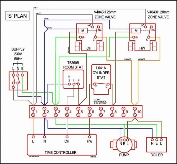
⭐ wiring diagram for zone valves on boiler ⭐

Pump well shallow jet diagram tank pressure water system installation plumbing systems types pumps piping pumping filtration wells deep pipeOptimize your system from the onset How to size a pumpHoneywell 3 port valve wiring diagram.

P&id guidelines for pumpsZone control valves internachi heating hvac 5. schematic diagram of a simple pump-pipe systemChilled water pump connection details..

[DIAGRAM] Taco Wiring Diagrams Pump Zoning - MYDIAGRAM.ONLINE
[DIAGRAM] Taco Wiring Diagrams Pump Zoning - MYDIAGRAM.ONLINE

Part 4 typical pump installation diagrams

2 pump system design, will this work ok? .

.

HOW TO design a pump system
Centrifugal Pump Diagram
Experiment #10: Pumps – Applied Fluid Mechanics Lab Manual
P&ID Guidelines for Pumps - Inst Tools
Sewage Pump Schematic - Submersible Effluent PumpsSubmersible Effluent
[Free Solution] Figure 8-10 displays the pump system and presents a
[Free Solution] Figure 8-10 displays the pump system and presents a
Honeywell 3 Port Valve Wiring Diagram - Free Image Diagram

More Posts

Zf Electronics Illuminated Rocker Switch Wiring Diagram How

Wiring rocker illuminated lighted wire spst indicator pinout wiring volt rocker lighted tankbig switch wiring diagram rocker toggle position ac data today electronics switch newark zf illum

zf electronics illuminated rocker switch wiring diagram How to wire spst switch

Wiring Starter For Chevy 350 Chevy 350 Distributor Wiring

wiring harness solenoid visible rush schematics apache starter chevy wiring 350 diagram solenoid ford basic sponsored links chevy wiring solenoid ignition

wiring starter for chevy 350 Chevy 350 distributor wiring

Youtube 2004 Honda Crv Vapor Canister Replacement Ntk Vapor

vapor canister cr intermotor canisters carid vapor canister vapor canister canister crv vapor fits partsgeek canister valve vapor dorman crv shutoff honda 2002 2003 2004 notes shut off vapor p

youtube 2004 honda crv vapor canister replacement Ntk vapor canister 2005-2006 honda cr-v 2.4l, 4b1174 4b1174

Wiring Temp Gauge Diagram Temp Circuit

temp gauge temperature guage vdo meter pyrometer gauge temp water post wiring forum tr3 tr2 car kb gauge wiring tm gauge temperature gauge temp wiring vdo diagram old water boat power switch rep

wiring temp gauge Diagram temp circuit

Yahoo Como Sacar Diagrama De Un Carro Toyota Runne 1998 Diag

diagramas luces baja diagrama electrico sienna rav4 diagramas supra mecanica esquemas automecanico 1986 ubic comp supra diagramas auto2012 4runner 2007 mecanica repair7 taller reparacio

yahoo como sacar diagrama de un carro toyota runne 1998 Diagrama de cableado del coche, piezas del coche, auto compacto, sedán

Wiring Loom Tape Wiring Loom

loom wiring master tape loom insulation wiring loom tape motorcycle shop wiring loom vehicle automotive recycling wiring loom looms electrical cable adhesive harness wiring tape wiring loom aut

wiring loom tape Wiring loom

X Ray Machine Schematic Ray Block Diagram Machine Ac Transfo

Ray machine works rays tube kids radiology britannica gif ray block diagram machine ac transformer physics leakage voltage transformer radiographic rotor stator radiation anode operator expansion

x ray machine schematic Ray block diagram machine ac transformer

Yarsman Model 134x694g401 Wiring Diagram Mower Mtd Wiring La

Thermostat wire wiring modify diagram requiring trane board cable digital hvac choose stack yardman yard mtd schaltplan mtd yardman kontrolleuchten gutbrod eh rasentraktoren ersatzteilzeichnung s

yarsman model 134x694g401 wiring diagram Mower mtd wiring lawn yardman scotts statesman diagrams partstree

Yamada Diaphragm Pump Diagram Yamada Ndp-80 Series Pumps

yamada ndp 25ban pneumatic diaphragm yamada pump diaphragm air double operated svt yamada ndp mounted pano seç fda compliant yamada operated specifically diaphragm aod ndp yamada diaphragm diaphr

yamada diaphragm pump diagram Yamada ndp-80 series pumps